
|
|
back |
|
Private
|

Capacitance
Capacitor: capacitance
Independently of the capacitor shape the capacitance is defined as the ratio between the charge Q on the electrode and the voltage U between the electrodes.

The charge stored on electrodes of surface A separated by a dielectric material of permittivity ε , is given by the surface integral of the scalar product of the electric displacement D with the surface vector of the surface element dA

Capacitance
The potential between the electrodes is given by the line integral of E along the arc s: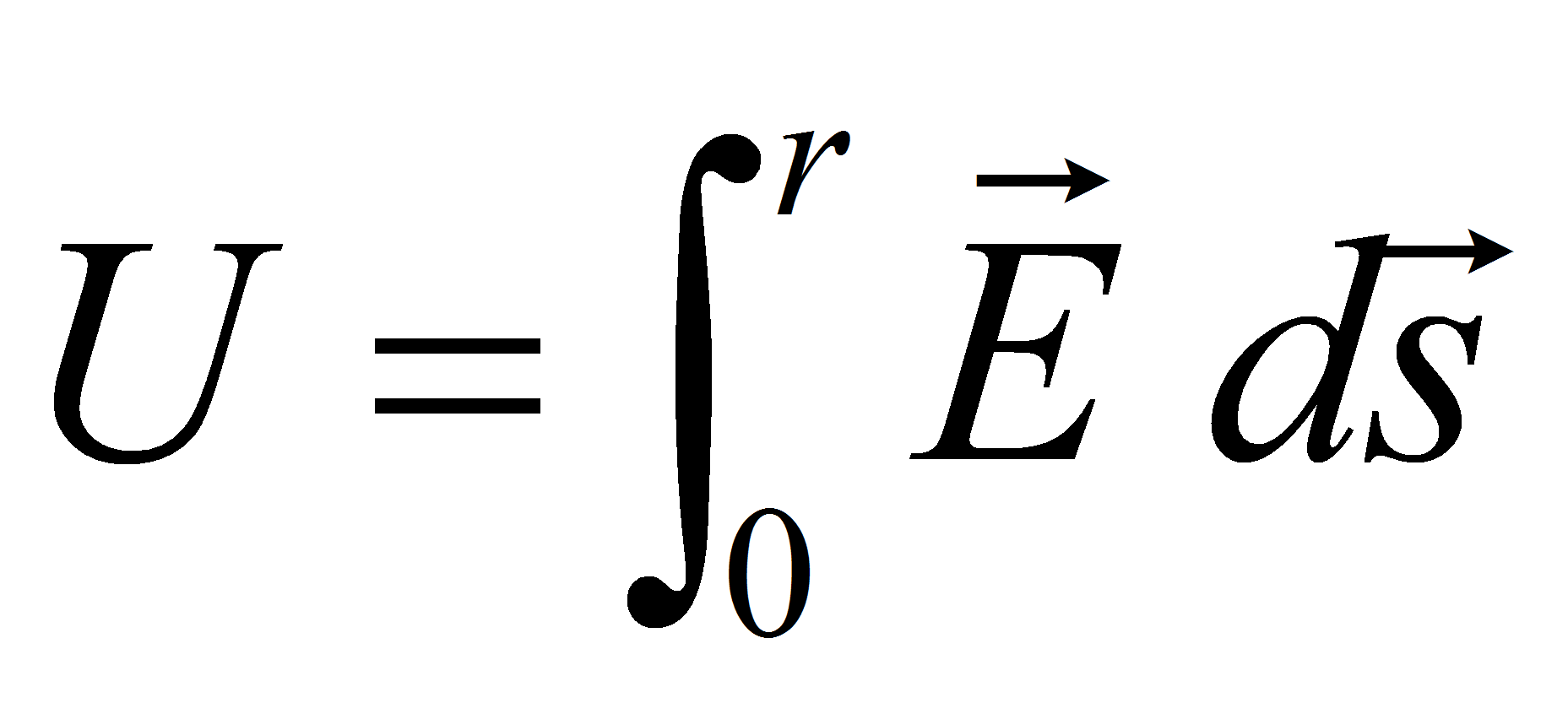
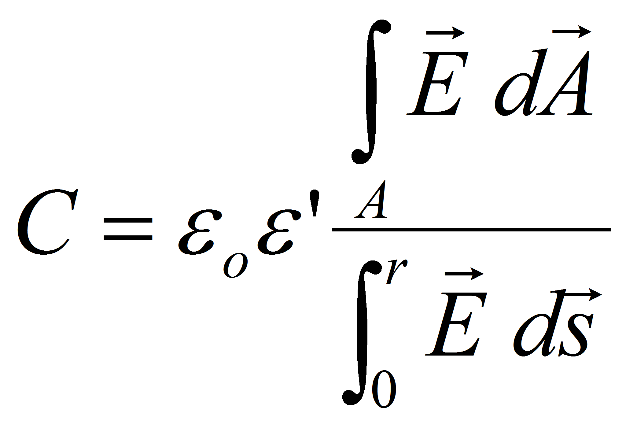
which leads to the expression of the capacitance
Capacitance determination
There are several methods used to determine the capacitance of a system:1)Approximation
2)Exact analytical method
3)Conform transformation
4)Graphical method
Approximation
In most of industrial capacitor the dielectric thickness d is much smaller than the electrode surface. In this case it's sufficient to perform the calculation with the approximation of flat parallel electrodes.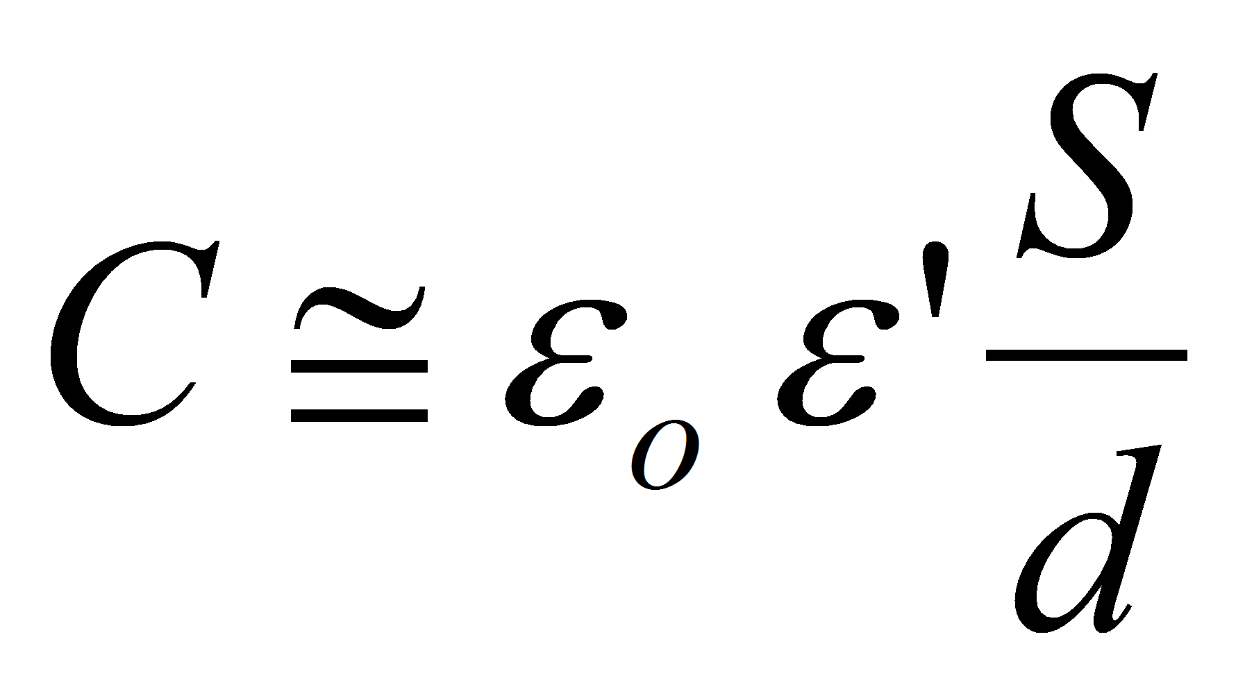
In this approximation the capacitance doesn't depend on the electric field E.
Exact analytic method
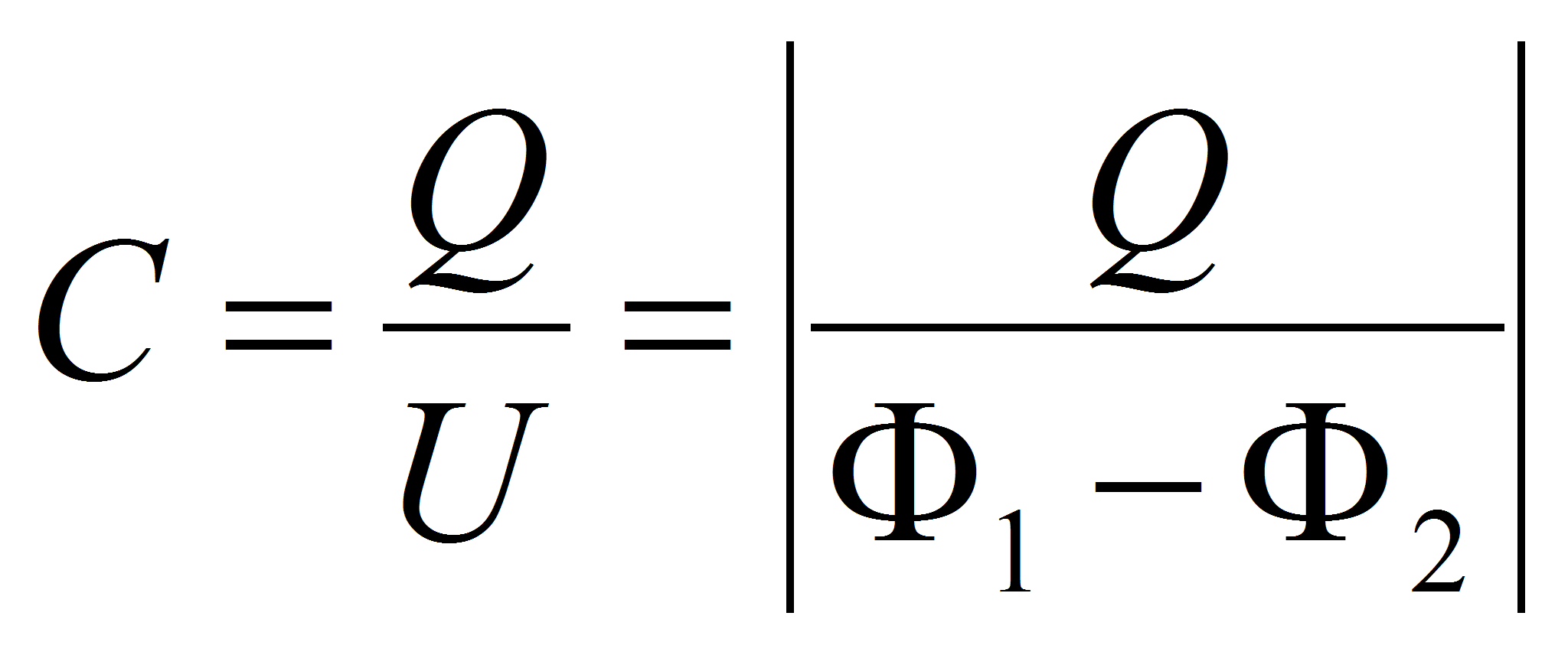
From Laplace lawThe capacitance is calculated with
Example: spherical capacitor
The potential of a point charge is given by
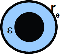
The capacitance is given by:
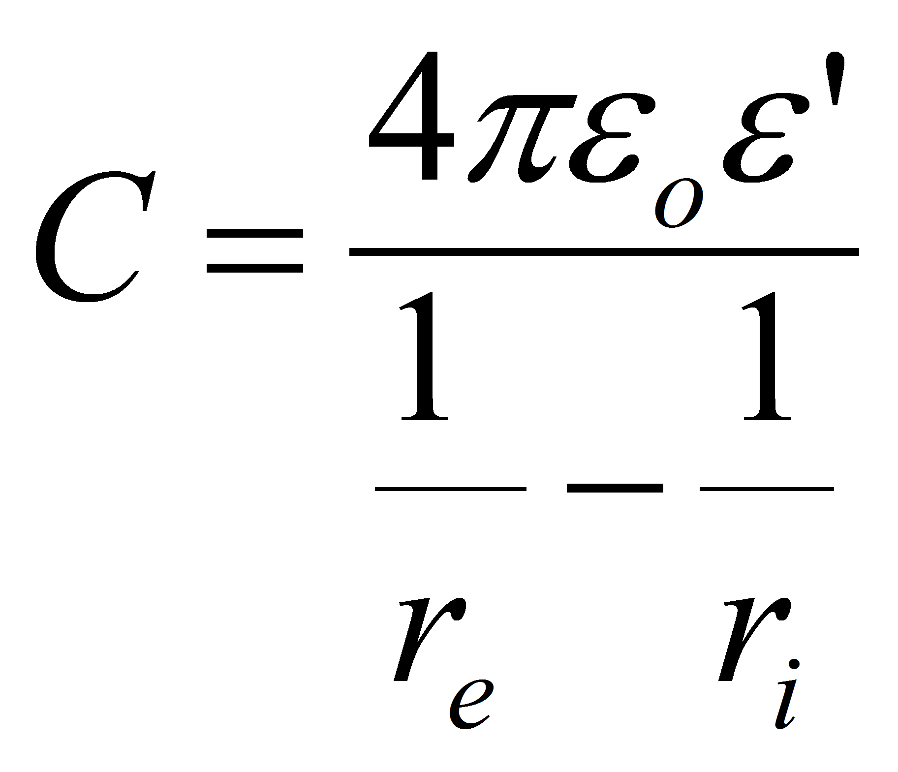
Where re is the radius of the external electrode, ri the radius of the internal electrode and ε the dielectric permittivity of the material which between the 2 spheres.
Conform transformation
An interesting method for calculating the capacitance is to use the conform transformation between complex surfaces. The 2 dimensional Laplace equation is used as transformation functionExample: cylindrical capacitor
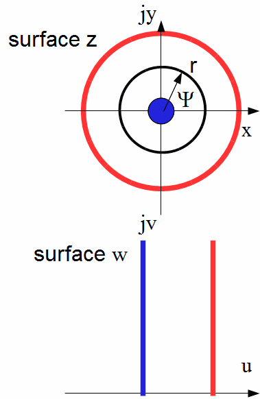

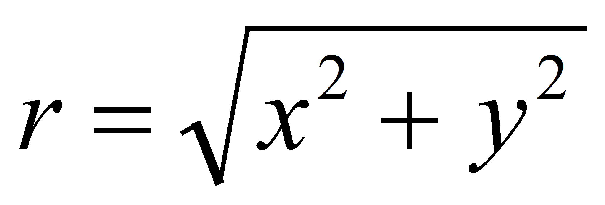
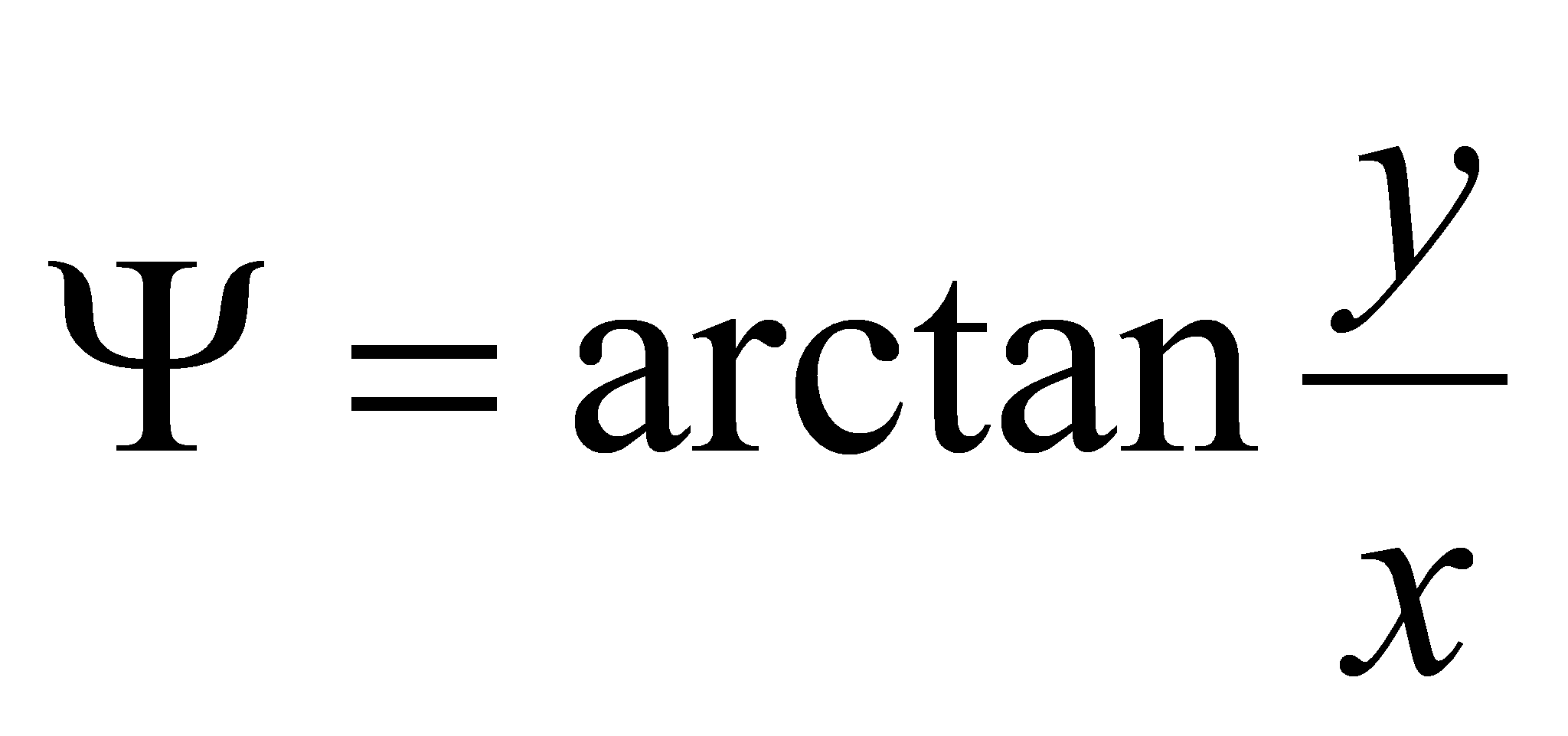
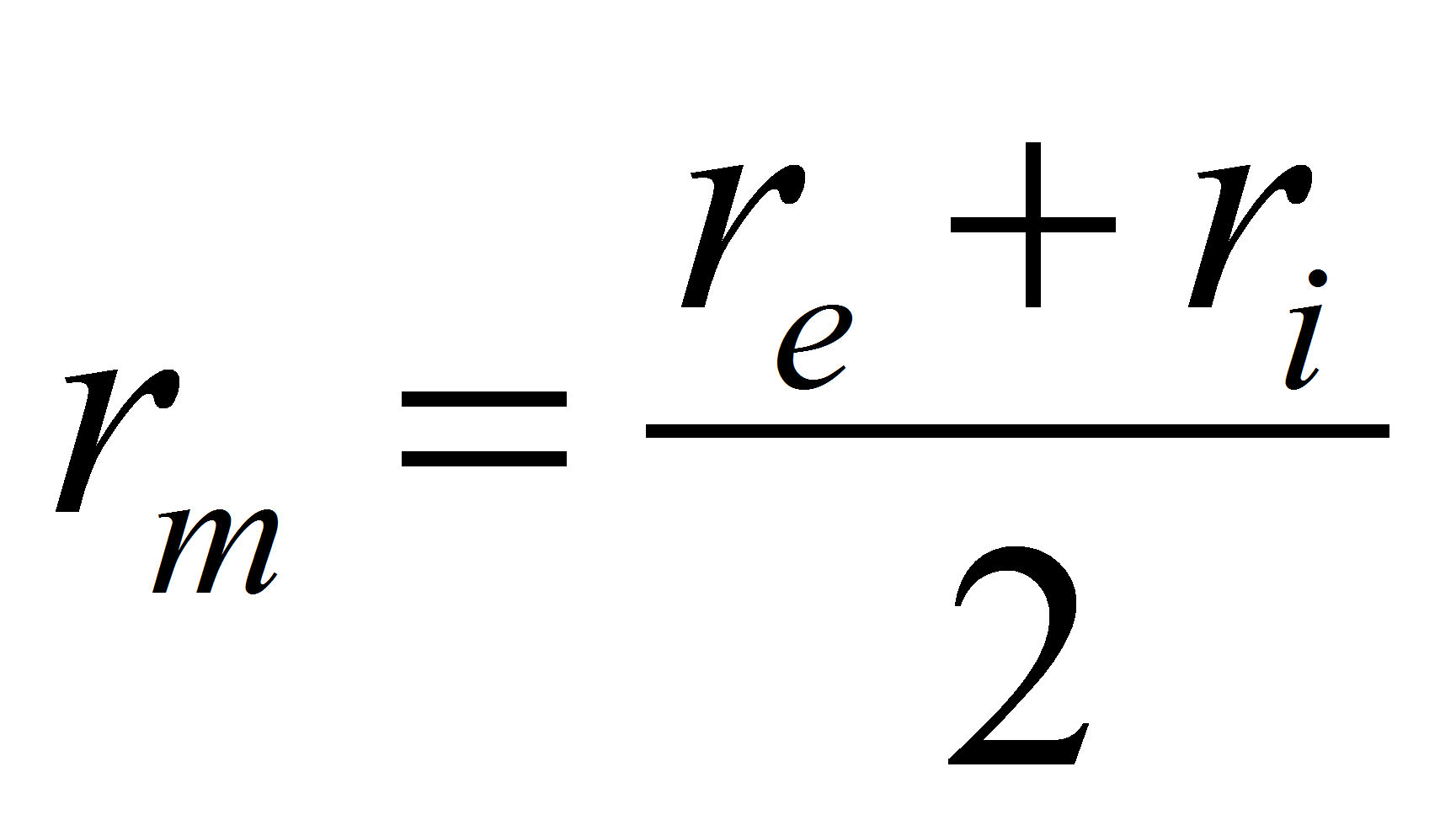
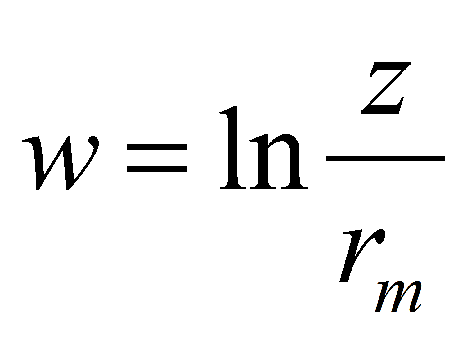

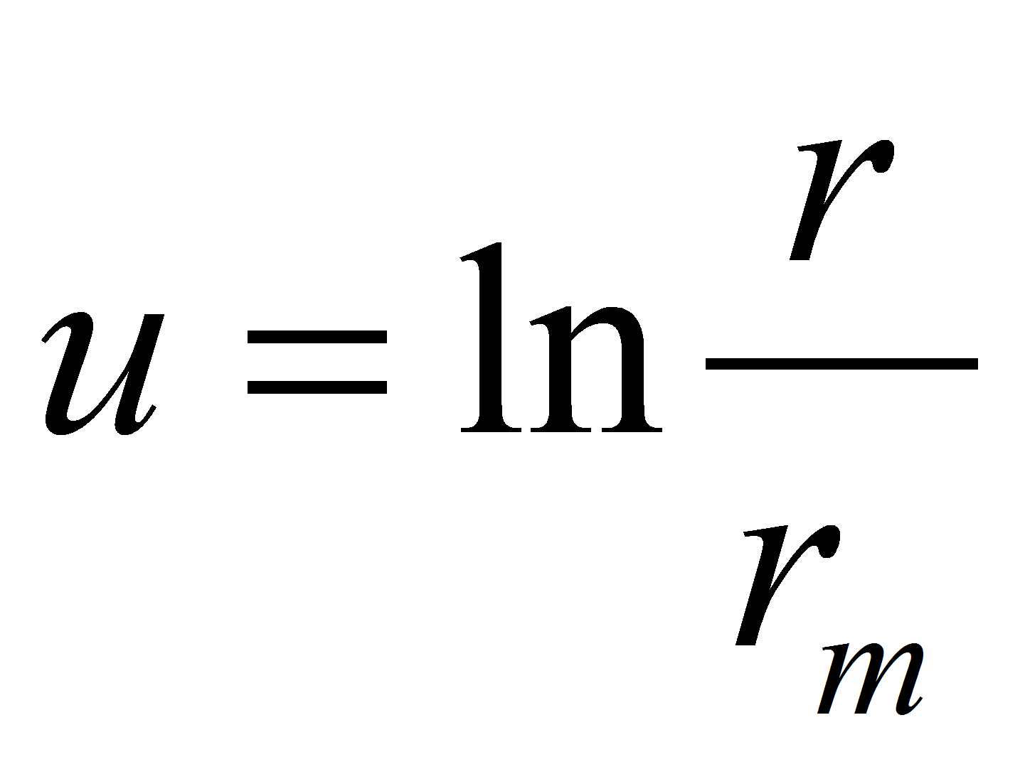
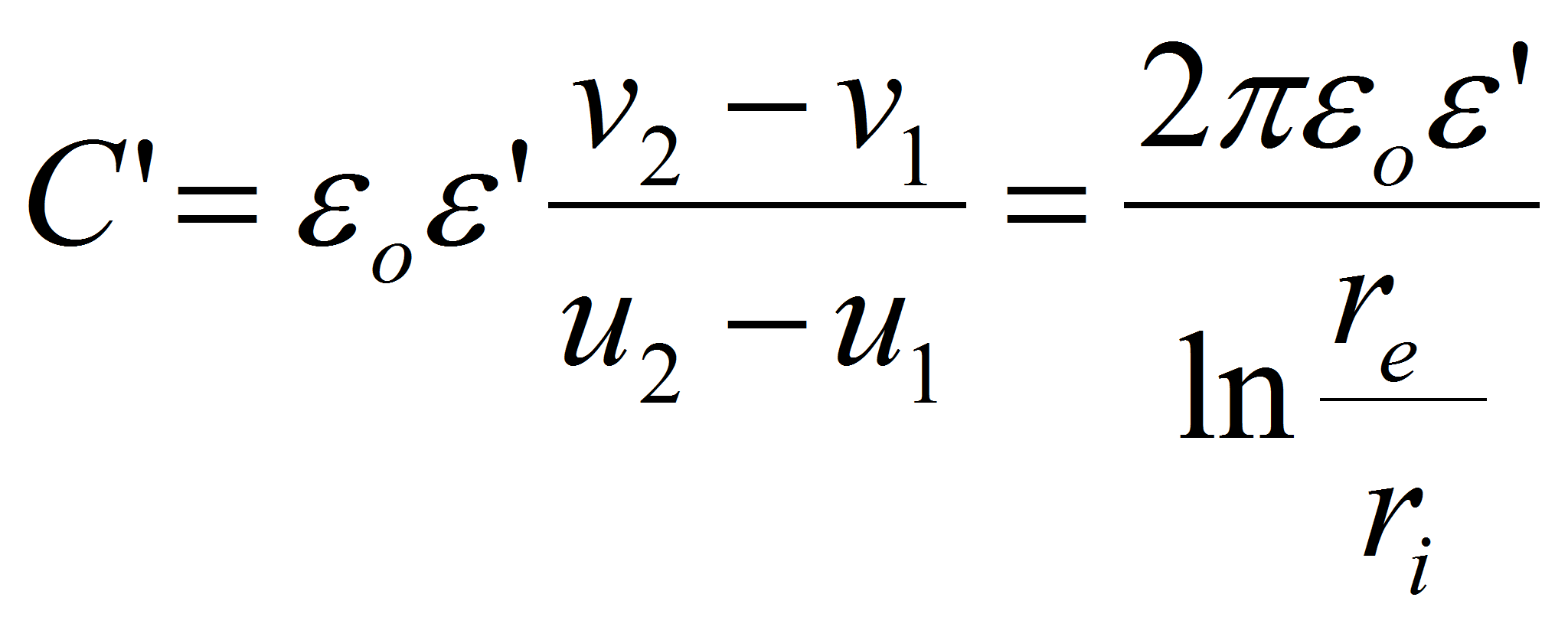
The capacitance per unit of length is given by
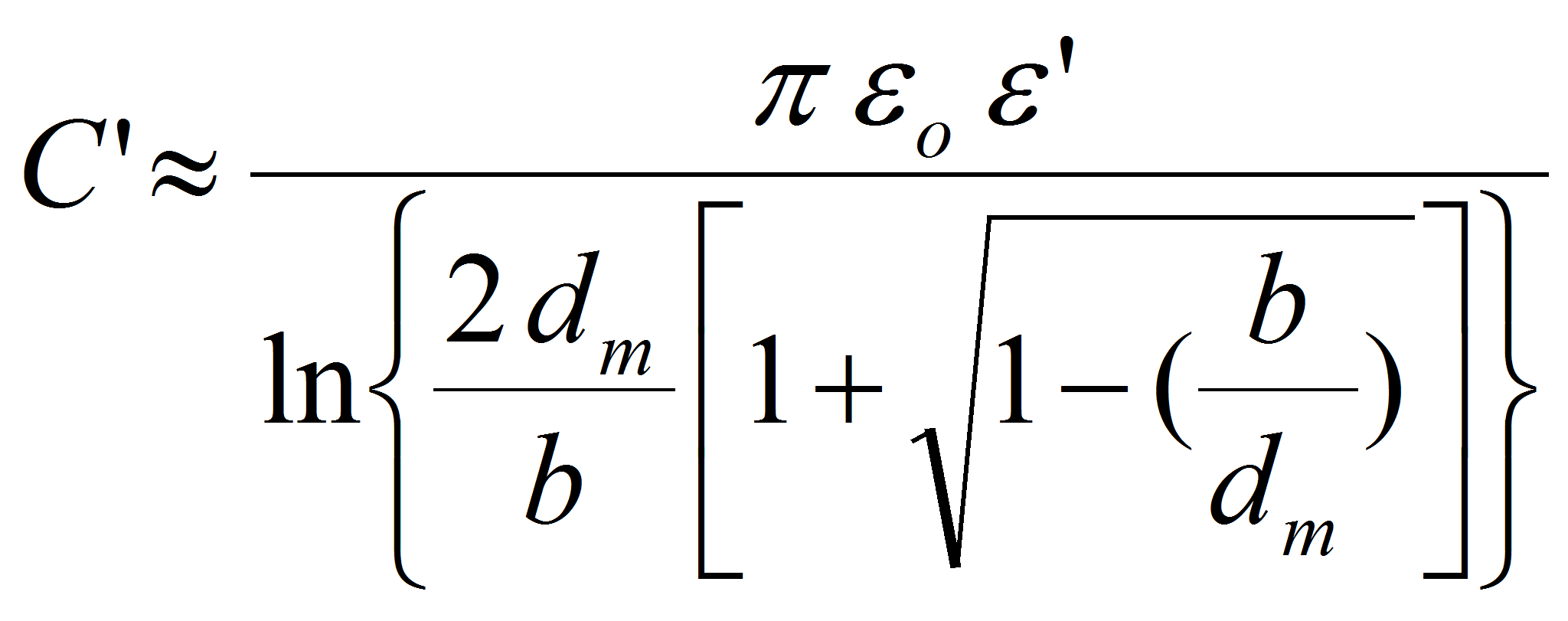
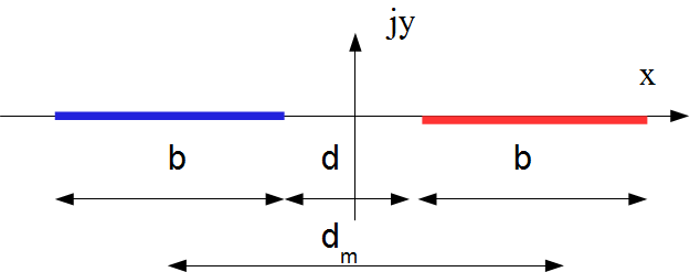
Example: conductive planar bands
The thickness of the bands is supposed to be very thin. The calculation requires elliptic functions.
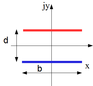 The solution for the capacitance per unit of length is given by:

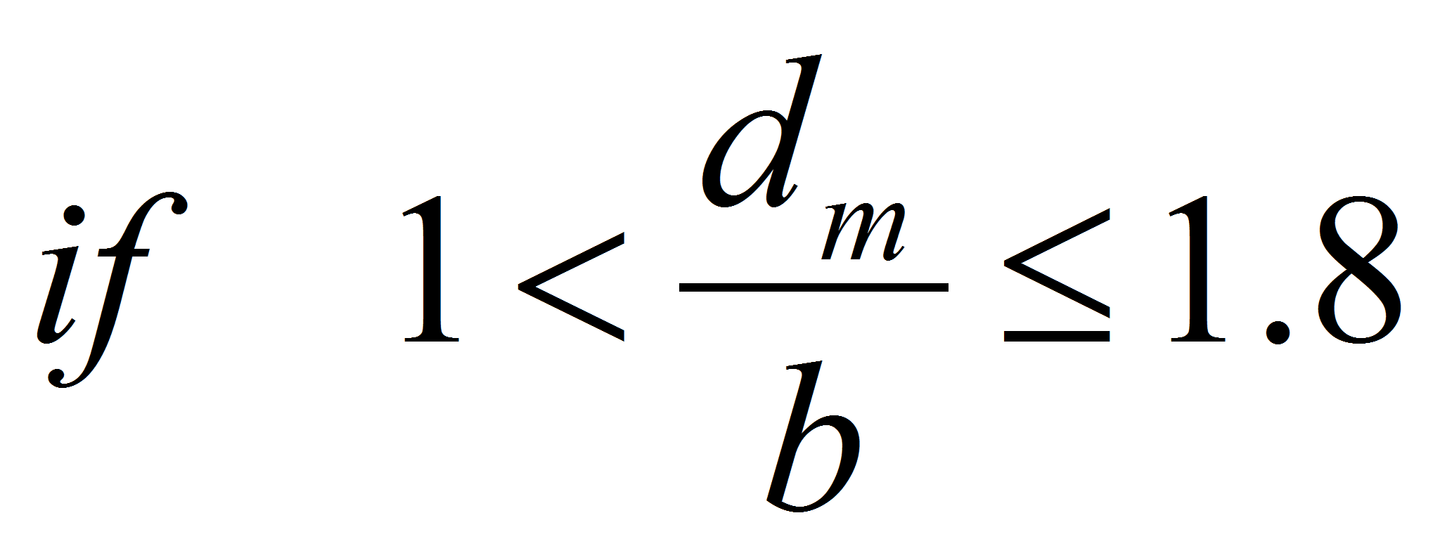
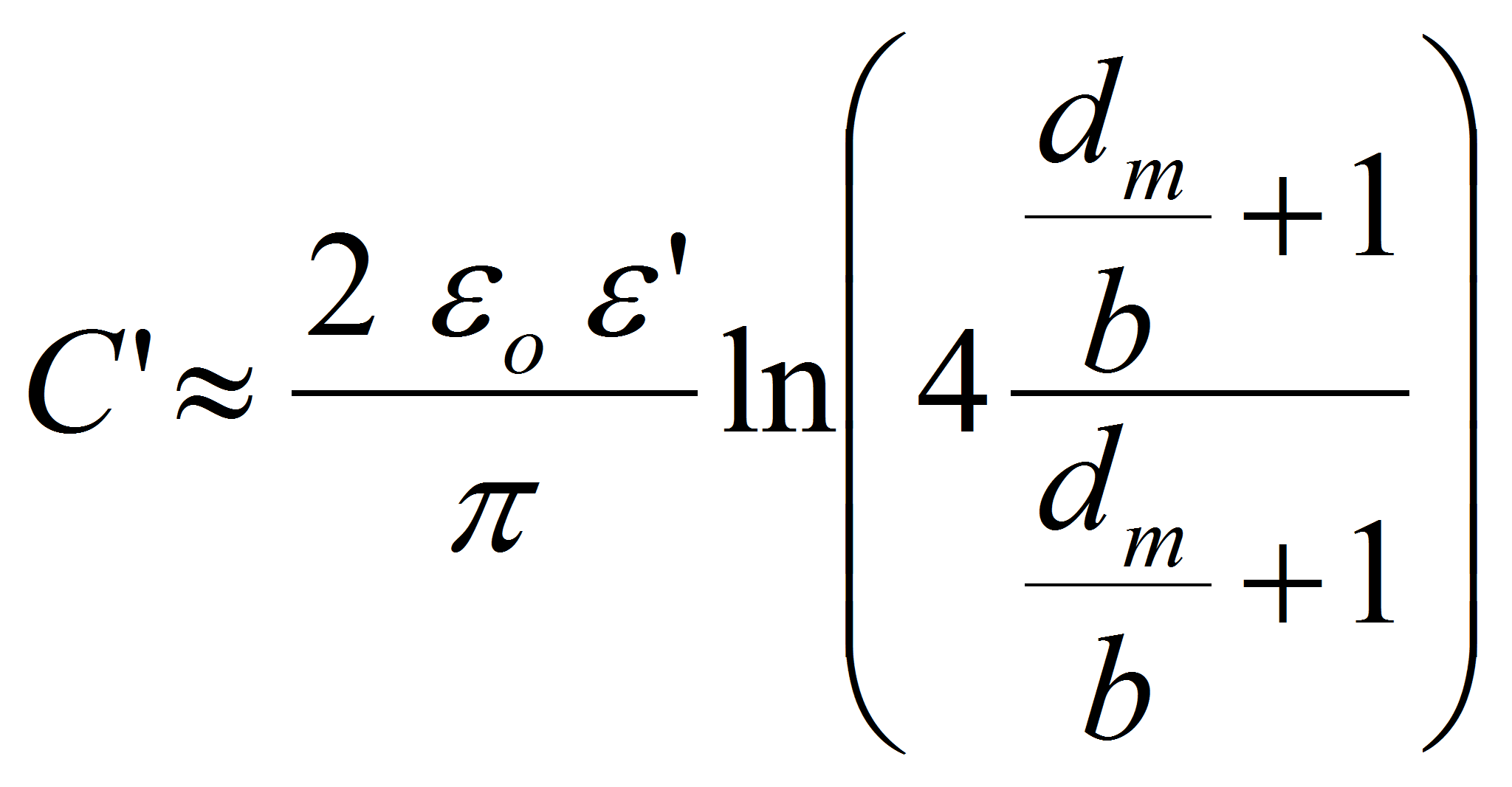
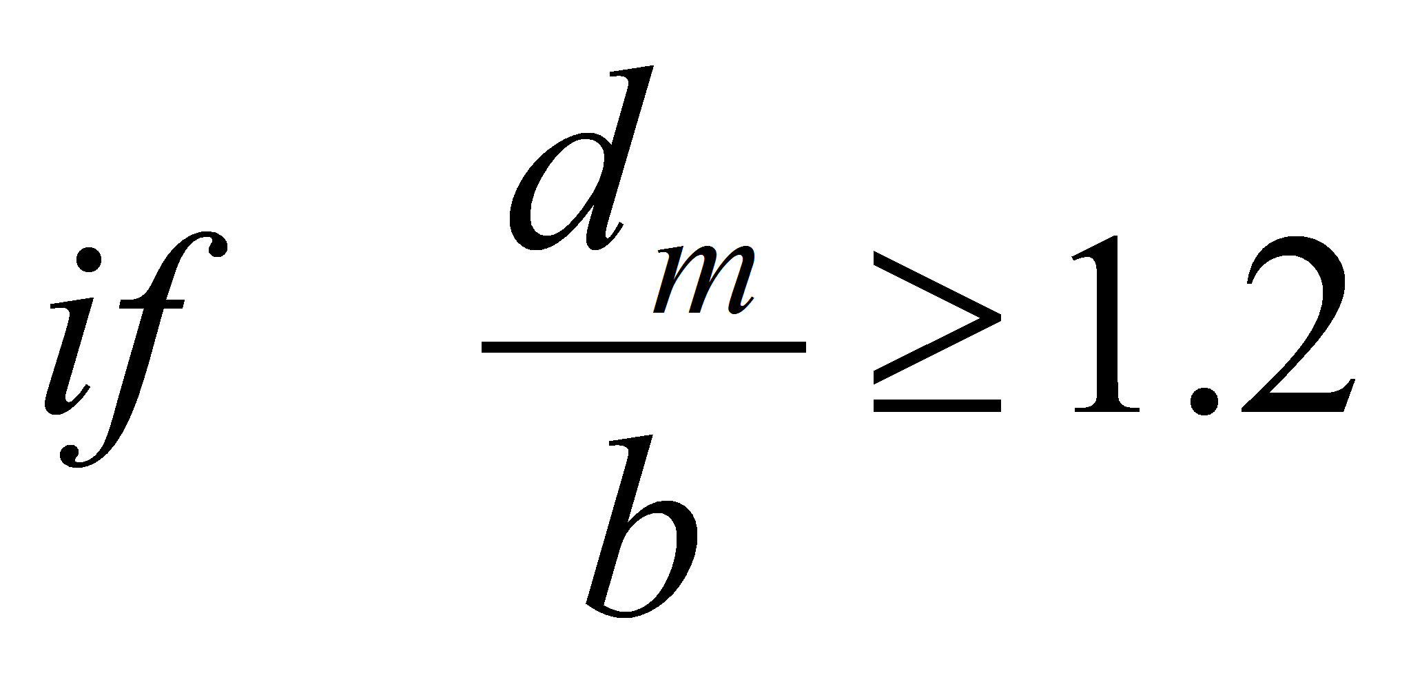
In the next geometry the general solution is the same. The approximation differs and gives the following result:
Rounding the electrode hedges
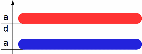
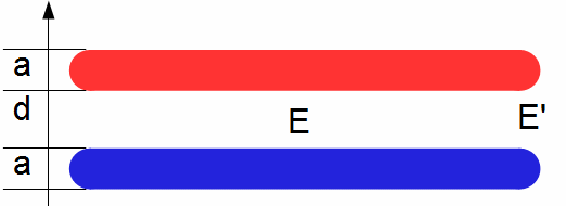
The sharper the electrode hedges are, the larger is the electric field close to the hedge. It's often at this place that partial discharges or breakdowns are initiating.Given an electrode thickness a, a rounding radius ρ and a distance between the electrode d, two cases must be distinguished:
Case 1: the electrode thickness 2a << d the distance between the electrodes
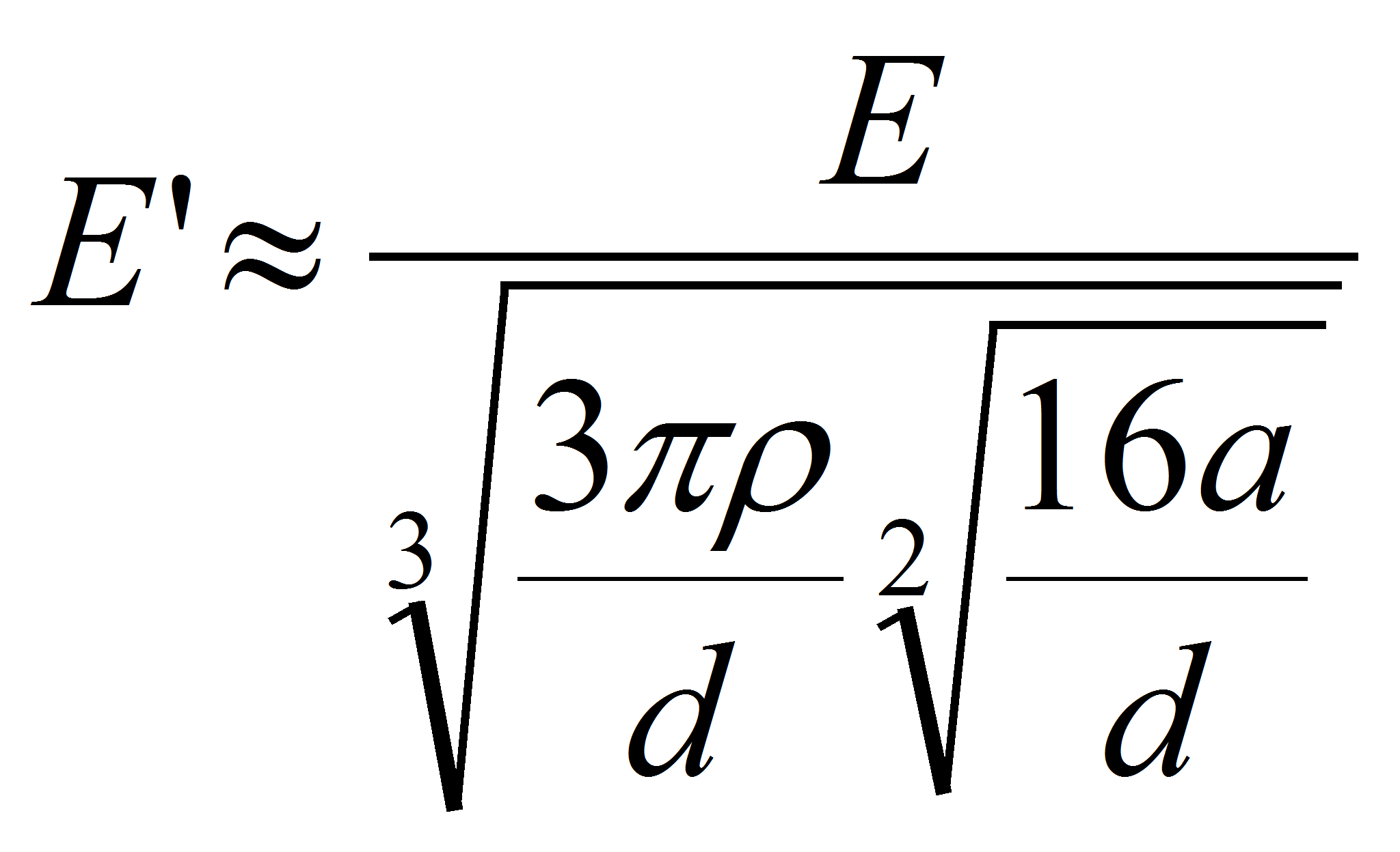
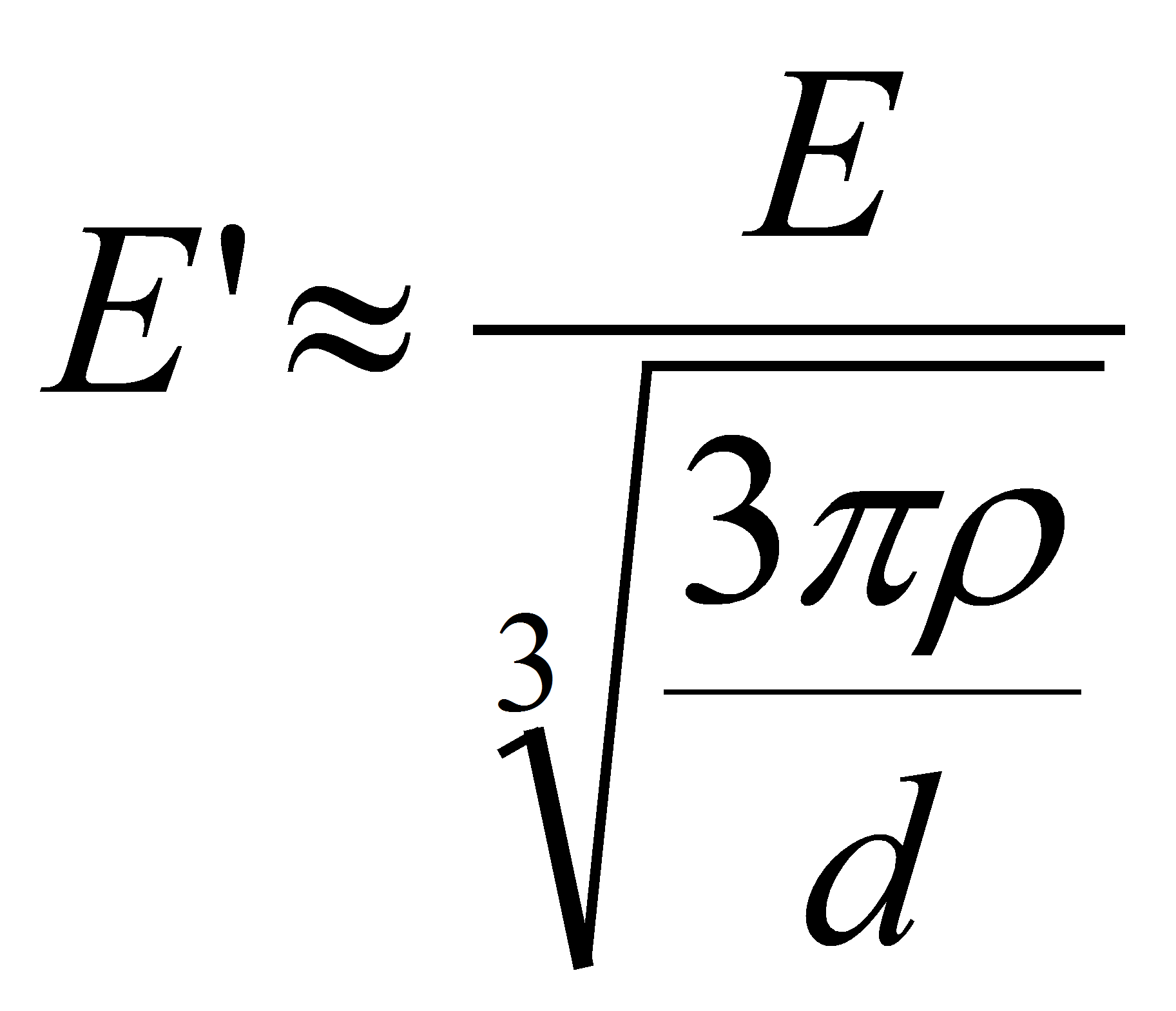
E is the electric field in the center of the capacitor where it is homogeneous,
E' is the electric field close to the hedge,
a is the electrode thickness,
d is the distance between the electrode,
ρ is the rounding radius.
Case 2: the inverse situation where 2a > d
Geometry: winding
A winding is a spiral made of 2 electrode bands and 2 dielectric systems.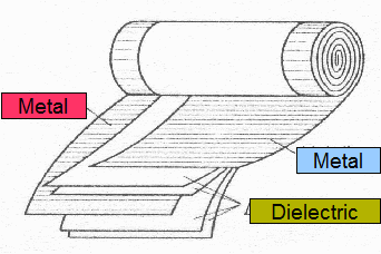 Each of these dielectric system is composed of one or a plurality of different dielectric films which can be (paper,
polypropylene (PP), polyethylene terephtalate (PET), ….).
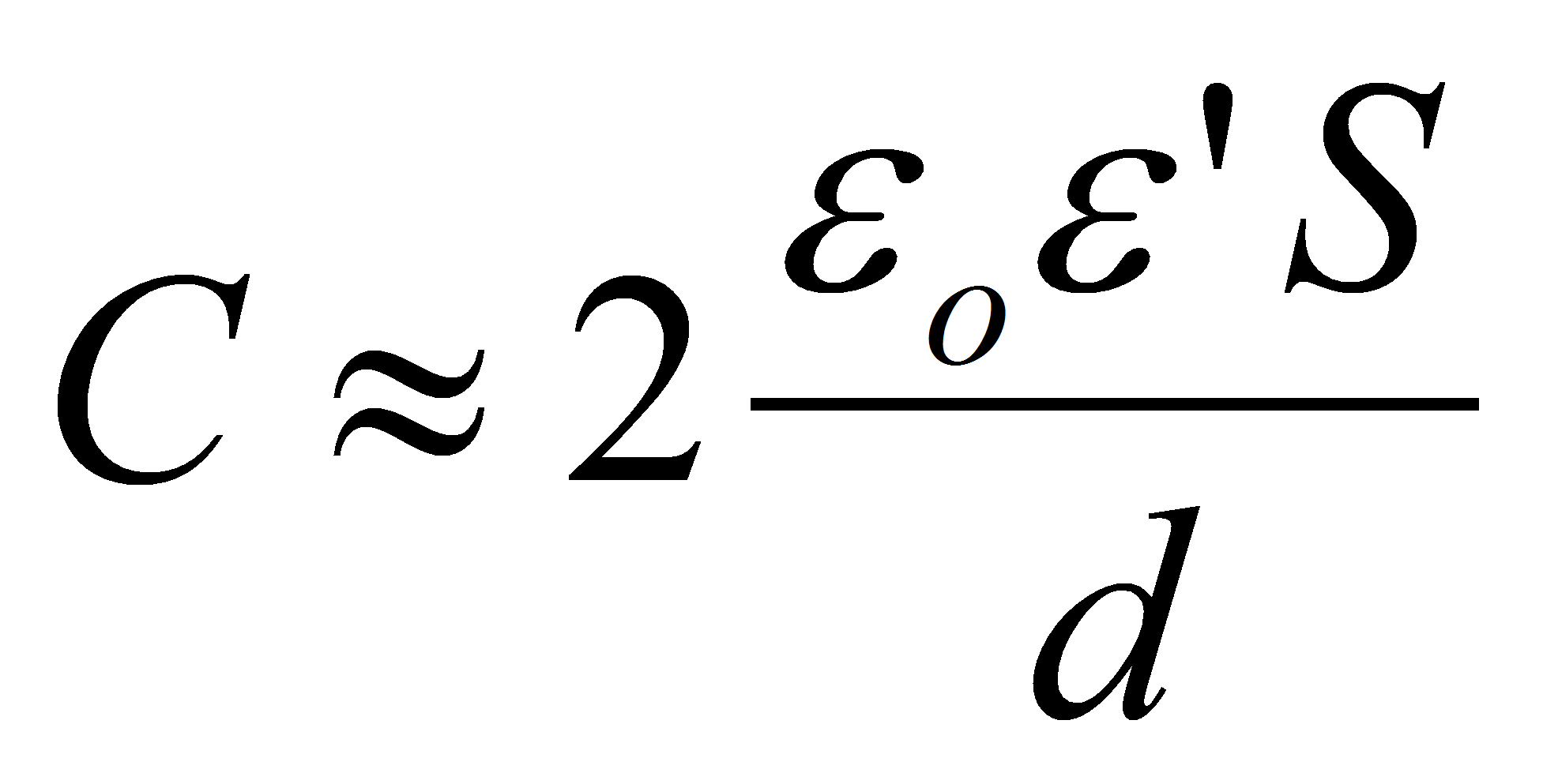
S is surface of the active part of the electrode band. S = electrode length L x electrode width W.
Geometry II: Ceramic capacitor and feed through capacitance

Source: Garmanage: Roland Gallay