|
|
|
back |

Frequency
Tangent delta frequency dependance
If the inductance Ls is neglected and for frequencies well below the natural resonant frequency, the dissipation factor tan delta is a combination of a parallel component tan deltap, a series component tan deltas and a dielectric component tan deltad:
tan delta = tan delta p + tan delta s + tan delta d
tan deltap = 1/(Rp 2 pi f C)
tan deltas = Rs 2 pi f C
tan deltad = a characteristic of the dielectric
where f is the frequency.
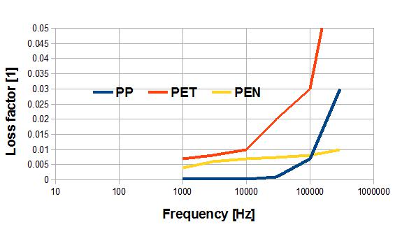
The parallel component tan deltap depends on the insulation resistance (parallel resistor Rp). Due to the extremely high values of insulation resistance, this component is negligible in the entire frequency range and contributes virtually nothing to the overall dissipation factor even at very low frequencies (f << 1 kHz). The dielectric component tan deltas is a measure of the losses associated with the dielectric (i.e. the energy wasted to polarize and repolarize the dielectric in two opposite directions for successive half-cycles of the AC voltage). It determines self-heating at low frequencies: In polypropylene capacitors, tan deltad remains approximately constant with frequency and will typically result in a value of approx. 10-4. In polyester capacitors, tan deltad is considerably greater and increases with frequency. So these capacitors display noticeably higher, overall dissipation factor at lower frequencies.
The series component tan deltaS is determined by the series resistance (RS), which represents the sum of the contact resistances and the resistances of leads, metal layers and electrode foils. This component increases rapidly with frequency until it becomes the dominating component in the tan delta curve for high frequencies. It also increases with capacitance.
Frequency dependence of dissipation factor tan delta, e.g. for CR = 0.10 microF (typical behavior)
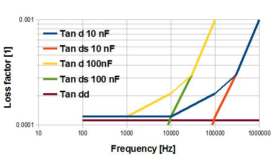
Dissipation factor tan delta vs. measuring frequency f (schematic representation using two polypropylene capacitors of different capacitance as examples)
Capacitor impedance linearily drops with the frequency. The consequence is that for a given voltage the current increases linearily with the frequency. The losses are proportionnal to the capacitor series resistance rs (contacts, conductors and metallization resistance) and to the square of the current. The capacitor temperature increase due to the losses is proportionnal to the loss power Ploss and to the thermal resistance Rth.
Delta T = Rth Ploss
For mechanical reasons the temperature increase in capacitors is tolerated until 15C.
It's considered that above this practical value, the capacitor may be damaged. In order not
to overcome this temperature increase, it's necessary to decrease the voltage linearily with the frequency to maintain a constant current and
to keep the same losses.
In the low frequency domain the limitation is given by the dielectric partial discharges.
In an intermediate frequency domain the limitation is given by the dielectric losses.
Source: Epcos-TDK, modified by Garmanage: Roland Gallay